


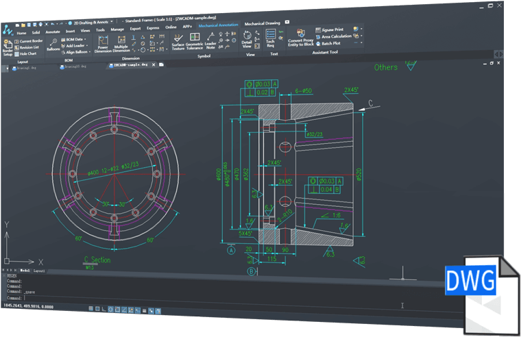
1. Professional 2D sketch for mechanical drawing
ZWCAD Mechanical for manufacturing provides a wide range of tools such as shaft generator, tolerance dimension, surface texture symbol, balloon and BOM, and standard 2D mechanical drawing components.

2. Easy to use and 100% compatible with DWG format
3. Smart Annotation
 |  | |
Power DimensionPower Dimension with a reduced dialog box that controls and expands with only production-related variables makes dimensioning easier. Attached the integrated tolerance and the appropriate listing information. | Multiple DimensionsWith Multiple Dimensions, you can create multiple dimensions with minimal input and coordinate the appropriate distance, parallel or symmetric items. | |
 |  | |
Detect overlapping dimensions and determine appropriate distanceOverlapping dimensions can automatically create proper spacing. This determination is based on objects of similar dimensions, making linear dimensions neat and clear. | Design quickly using Mechanical symbolsMechanical symbols, including textured surface symbols, datum identifiers and targets, taper, center holes and weld symbols are very time-saving and improve your design accuracy. |
 |  | |
Easily create balloons and BOMWith ZWCAD Mechanical, you can draw, arrange and renumber standard ballons easily. It only takes one step to create a BOM. In addition, it automatically recognizes standard components, summarizing them into BOM. | Collaborate, link Balloon and BOMAny changes on the balloon will be updated to BOM, ensuring that the data is always correct and latest. |
4. Smart drawing environment
 |  | |
Support international and enterprise standardsZWCAD Mechanical supports drawings with ISO, ANSI, DIN, JIS and GB standards, it also provides customizations to conform to enterprise standards. | Layer management and layer mappingEach mechanical entity, such as borders, dimensions, symbols, etc., will be placed into the default layer with the preset color and linetype. With layer maps, mechanical entities can be placed on a custom layer to match company standards. | |
 |  | |
Multiple borders and adaptive scalingZWCAD Mechanical supports drawings with multiple borders of different sizes, and the size of annotation objects can be changed according to the size of the border. | Super EditRetouching is easy, double-clicking the object and then the settings in the dialog box will change automatically. |
5. Mechanical Parts and Generator
 |  | |
Part LibraryZWCAD Part Library contains screws, nuts, washers, pins, rivets, springs, bearings, etc. Save you time when using this library for design. | Shafts and GearsYou can create Shafts and Gears by entering geometric parameters, which speeds up the design process. |
6. Extensive tools for production drawings
 |  | |
Construction linesIncludes a total of 32 options to create construction lines and 7 options to create construction circles. Construction lines can be used as references for other drawings to help make drafting more convenient in the design. | Advanced CenterlineYou can add centerlines to circles and rectangles by selecting simple objects. Centerlines can be retrieved from one entity or multiple. | |
 |  | |
Reusable detailing toolsGenerate the detail view with a few clicks, and it is updatable when a change is made to the geometry. | Draw Groove quickly and accuratelyTechnical grooves are an important part of the mechanical design process, and ZWCAD Mechanical provides a wide range of structural building features, including cracks, shafts and hole rect reliefs. |